This way of modelling presented in this post is one of most used, as it is simple and sufficiently accurate. For the fastener modelling generally is used a Spring type element (CBUSH), and it should be done as Mesh-indipendent, like a no direct node-to-node connection (usually a RBE3 is used).
Elastic properties
The fastener flexibility is a measure of the influence of fasteners (rivets, bolts, etc.) on the flexibility of the whole joints. It is important to evaluate the factors influencing the strength and the fatigue life of an aircraft joint. In general the flexibility can be defined as: C=1/Stiffness (Ki) = L/F. F refers to the external force and L to the deflection of the joint due to the fastening.
For the CBUSH, the elastic properties to used are:
- Axial Stiffness
K1 = E*S / L, with E=Fastener’s Young module, S=fastener section area, L= Fastener’s length.
- Shear Stiffness
Measured properties if available
K2=K3=1/C,
The most conservative formula for the shear flexibility is the Huth formulation:
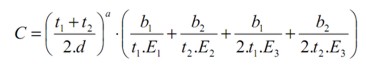
C: Flexibility of the fastener
t1 : thickness of plate 1 (or plate 2 for the second step)
t2: thickness of plate 2 (or plate 3 for the second step)
E1: Young modulus of plate 1 (or plate 2 for the second step)
E2: Young modulus of plate 2 (or plate 3 for the second step)
E3: Young modulus of fastener
a : Coefficient depending on the fastener type (2/3 for metallic and graphite/epoxy bolted,2/5 for riveted metallic)
b1, b2 : Coefficients depending on the joint plates material. b1=b/n and b2=b/n^2, with n=1 for single shear and 2 for double shear, b is equal to 3 for bolted metallic, 2.2 for riveted metallic, and 4.2 for bolted graphite/epoxy.
- Rotational Stiffness
When a contact is not modelled, a minimum value for rotational stiffness is recommended. The rotational stiffness (K5 andK6) has to be calculated as a function of higest shear stiffenss and the CBUSH element length:
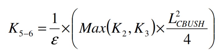
with 1/ε = 100, and LCBUSH is the CBUSH length, (distance between the modeling reference planes of the joint plates. Alternative way is to use a magnitude of 10^9 for K5 and K6. Rotational Stiffness around the fastener axis K4 can be fixed to 100.
CBUSH orientation
The CBUSH Coordinate System is generally defined as follows : X axis is given by the 2 Nodes defining the element. Y axis is determined by a user defined Orientation Vector lying in the (X,Y) plane (see figure below).
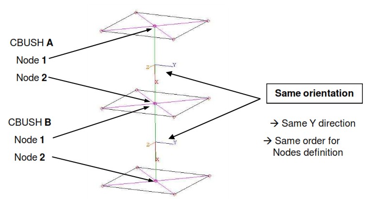
The Y axis can be oriented parallel to one of the 0°material axis of the connected plates if composite materials are involved (for example, positive X aircraft axis for fuselage skin and stringer). It is recommended to have the same bush orientation for all fasteners that are perpendicular to the same plane (i.e. Fasteners belonging to the same structure). it is recommended to have the Element Coordinate System oriented in the same way for all CBUSH elements defining one fastener in multi-plate joint. Therefore, nodes 1 and 2 of CBUSH elements have to be defined in the same order/direction through the bolted joint (see the figure above).
Limitations
Even if this kind of modelling gives a good approximation, axial loads can only be calculated accurately using contact modelling (by introducing the CGAP element). It is possible by one spring-type element through the thickness, combined with contact modelling.