1 . Analysis of the Orthotropic Lamina
1.1. Introduction
1.2. Hooke’s Law
1.3. Relationships between elastic constants and Matrix of Elasticity
1.4. Matrix of Elasticity
2. Classical theory of Laminates
2.1. Introduction
2.2. Basic Formulas
2.3. Laminate stiffener matrix
2.4. Calculation of Stress and deformation
2.5. Thermal Stress
2.6. Calculation of Elastic Constants
>> Composite Analysis Tool
In materials science, Composite laminates are assemblies of layers of fibrous composite materials which can be joined to provide required engineering properties, including in-plane stiffness, bending stiffness, strength, and coefficient of thermal expansion.
The individual layers consist of high-modulus, high-strength fibers in a polymeric, metallic, or ceramic matrix material. Typical fibers used include graphite, glass, boron, and silicon carbide, and some matrix materials are epoxies, polyimides, aluminium, titanium, and alumina.
Layers of different materials may be used, resulting in a hybrid laminate. The individual layers generally are orthotropic (that is, with principal properties in orthogonal directions) or transversely isotropic (with isotropic properties in the transverse plane) with the laminate then exhibiting anisotropic (with variable direction of principal properties), orthotropic, or quasi-isotropic properties. Quasi-isotropic laminates exhibit isotropic (that is, independent of direction) inplane response but are not restricted to isotropic out-of-plane (bending) response. Depending upon the stacking sequence of the individual layers, the laminate may exhibit coupling between inplane and out-of-plane response. An example of bending-stretching coupling is the presence of curvature developing as a result of in-plane loading.
A lamina of composite is builded up with unidirectional or bi –directional reinforcement andc the thickness is generally between 0.1 and 5 mm. It is used for the construction of laminates whose characteristics (thickness, number plates , orientation, etc. . ) are determined on the basis of specific project needs . The analysis of a laminate thus requires knowledge of the mechanical behavior of single lamina and in particular of its constitutive equations .
A foil of the composite element is a microscopically heterogeneous element since its composition is practically variable from point to point . From the macroscopic point of view , ie considering a scale larger than the size of the fibers , it can however be considered homogeneous . In this scale , in addition, it exhibits a mechanical anisotropic behavior, in particular orthotropic .
Anisotropy is the property of being directionally dependent (its characteristics vary continuously), as opposed to isotropy, which implies identical properties in all directions.
In particular, if the material has three planes of symmetry mutually orthogonal , it is called orthotropic.
In a composite laminate the plans are identified by the middle plane of the lamina and this orthogonal planes are parallel to the two principal directions (direction of the fibers and the direction orthogonal reinforcement for unidirectional fiber) . To better understand the difference between an anisotropic material and an orthotropic material is useful to observe – for example – that the application of a tensile load to an element with prismatic form and made with anisotropic material , produces deformations and variable flows along all element sides. This occurs regardless of the particular direction of the applied loading . Instead if the material is orthotropic , there are three directions mutually orthogonal such that the application of a tensile stress in these directions produces , like an isotropic material, a costant deformation without distortion in the plans identified by these (Figure 1 ) .
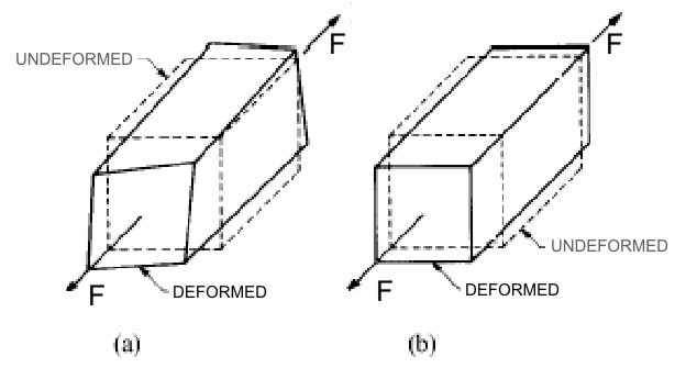
Figure 1
These three directions are called the principal directions of the material. Considering instead of a cube of material, a composite lamina, if the direction of application of the load coincides with a main direction (Figure 2 (a)) then corresponds to a normal stress simple a state of uniform deformation without sliding, while if the load direction is deflected with respect to the principal directions of the load also produces sliding in the plane (Figure 2 (b)).

Figure 2
[smartslider3 slider=”2″]